
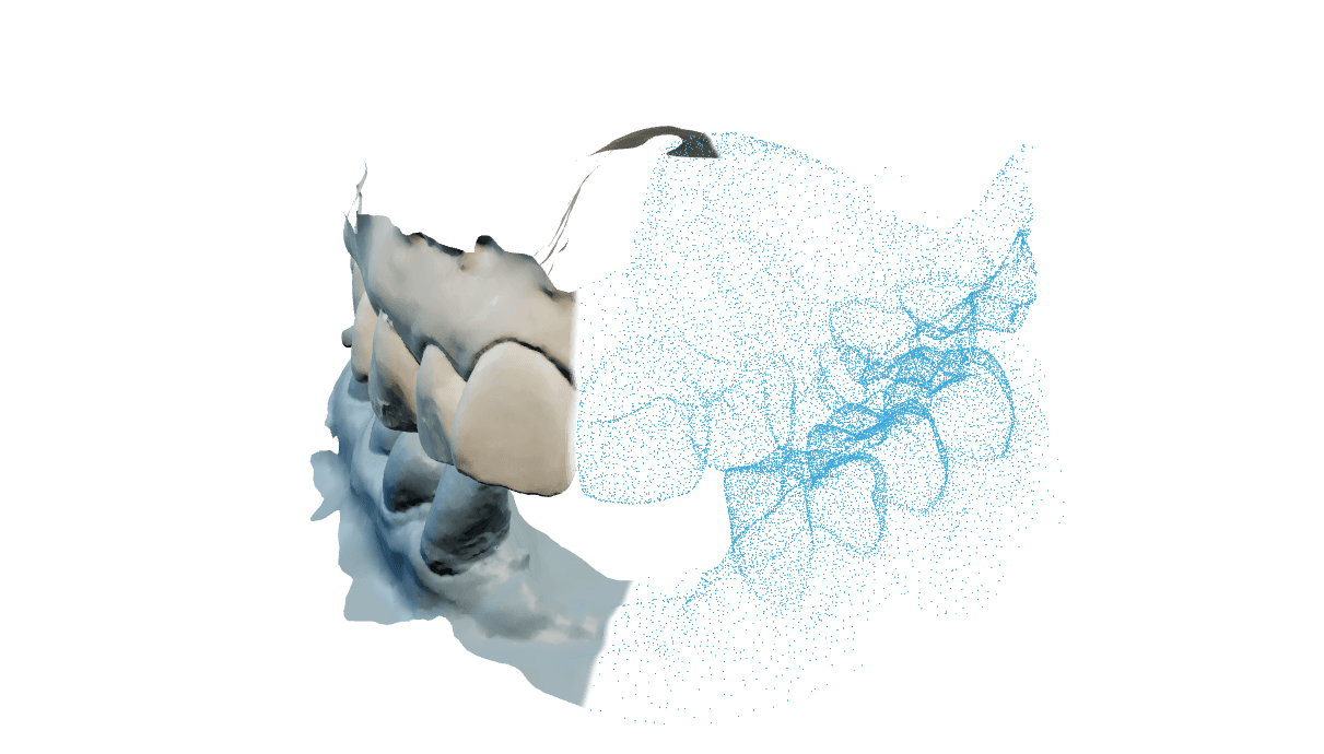
Einen Hybrid in Steg und Suprastruktur trennen
Split Bar nimmt einen fertigen All-on-X-Hybrid und trennt ihn in die beiden Teile, die Sie tatsächlich fertigen: den Steg, der die Implantatanschlüsse trägt, und die Suprastruktur, die darüber sitzt. Die Schraubenkanäle bleiben durch den Schnitt hindurch frei, und der Zementraum zwischen den Teilen ist Ihre Einstellung.
Alles wird in Ihrem Browser gerechnet, es reagiert also sofort und wartet in keiner Warteschlange. Die schweren Schritte verteilen sich auf bis zu 8 Arbeitsthreads, einen weniger als die gefundenen Kerne, und das Ergebnis ist bei jeder Threadzahl identisch. Wo Threads nicht verfügbar sind, läuft dieselbe Engine mit einem Thread: gleiche Geometrie, mehr Zeit.
Der Arbeitsbereich misst und zeigt, er zertifiziert nicht. Prüfen Sie beide fertigen Teile selbst und gegen Ihren Fertigungsprozess, bevor Sie sie klinisch einsetzen.
Die sechs Schritte der Reihe nach durchgehen
Orientation
Bestätigen Sie, wohin die Okklusion zeigt. Das Panel nennt die gemessene Neigung in Grad und bietet an, den Scan auszurichten; ein kopfüber angekommener Scan wird hier gedreht. Vor der bestätigten Orientierung wird nichts anderes freigegeben.
Implant sites
Setzen Sie eine Position auf jeden Implantatanschluss. Damit weiß die Konstruktion, wo der Schraubenkanal frei bleiben muss. All-on-X-Fälle tragen üblicherweise vier bis acht Implantate, und das Panel weist darauf hin, wenn es weniger als vier sieht. Jede Position trägt außerdem ein Schutzband von 0,2 bis 3 mm, vorbelegt mit 0,35 mm, das den Steg vom Anschluss selbst fernhält.
Randlinie
Zeichnen Sie die geschlossene Kontur, die den Steg begrenzt. Sie muss auf ihrem Startpunkt schließen, bevor der nächste Schritt öffnet. Das Panel warnt, wenn eine Position zwischen ihrem Schraubenkanal und Ihrer Linie weniger Raum hat, als Wand und Stufe zusammen brauchen, und nennt die Position.
Form
Wählen Sie die Grundform und formen Sie den Steg. Classic ist die allgemeine Form; Strip ist für FP1-Arbeiten und braucht mindestens zwei Implantatpositionen, sonst wird sie als Classic gebaut. Die Höhe reicht von 0,1 bis 30 mm ab 0,5 mm, die Auflagestufe von 0,5 bis 1,2 mm ab 0,55 mm, der Stegwinkel von 0 bis 24 Grad ab 0, und die beiden Verjüngungen nehmen 0 bis 2 mm aus der Mitte und 0 bis 1 mm je Seite, beide ab 0. Bei Strip stellen Sie zusätzlich die Stegbreite ein, 1,5 bis 4 mm ab 2,5 mm, und die Profilhöhe, 1,5 bis 6 mm ab 3 mm.
Verfeinern
Stellen Sie Feldspalt, Randspalt und Randzone ein und prüfen Sie danach die Ziel-Endstärke. Neue Fälle beginnen mit 0,200 mm im Feld, 0,075 mm an der exakten Abschlusslinie und einer Randzone von 1,000 mm. Der glatte Übergang beginnt genau danach und wird automatisch erzeugt. Die Ziel-Endstärke beginnt bei 1,000 mm; tragende Bereiche und Verbinder erhalten eine Fertigungswarnung für 2,000 mm Zirkonoxid. Die rote Führung und Material ergänzen verwenden dieselbe zementierte Fläche wie die endgültige Teilung.
Ergebnis
Führen Sie die Trennung aus und sehen Sie sich beide Teile an. Laden Sie sie als zwei Modelldateien herunter oder als Paket mit Steg, Suprastruktur und CAM-Datei zusammen. Der Arbeitsbereich vergibt absichtlich kein Bestanden-Siegel: er liefert die Messwerte, und Sie entscheiden.
Scan und Implantatpositionen vorbereiten
Der Steg wird gegen den Hybrid selbst konstruiert, das Modul nimmt also einen zusammengeführten Kiefer. Zwei getrennte Kiefer starten keinen Split-Bar-Fall. Ein Kieferscan kann als optionale Referenzgeometrie angehängt werden; er wird nur zur Orientierung gezeichnet und geht nie in die Konstruktion ein.
Exportieren Sie den Hybrid als ein zusammengeführtes Mesh, am besten mit der Option Ihrer CAD-Anwendung zum Anpassen für den 3D-Druck. Ohne sie exportierte Meshes tragen häufig kleine Flächenfehler, die sich später als raue Schachtwände zeigen.
Das ist die Einheitenprüfung: der Kiefer liegt außerhalb der 30 bis 90 mm, die ein echter Kiefer einnimmt, was fast immer bedeutet, dass nicht in Millimetern exportiert wurde. Es ist eine Warnung und keine Sperre, Sie können also weiterarbeiten, sollten aber in Millimetern neu exportieren, bevor Sie sich auf eine Messung verlassen.
Ja. Die Implantatanschlüsse und die Schraubenkanäle bleiben durch den Schnitt hindurch erhalten, genau darum wird gegen den Hybrid statt gegen einen einfachen Kiefer konstruiert. Kann ein Kanal den Steg nicht sauber durchqueren, hält der Aufbau an und nennt die Position, statt ihn zu verschließen.
Mindestens eine Abstützung, bevor ein Steg gebaut werden kann, und in der Praxis vier bis acht bei einem All-on-X-Fall. Die Form Strip braucht mindestens zwei Positionen, weil sie ihren Rücken zwischen ihnen führt.
Im Browser arbeiten, ohne etwas zu verlieren
Konstruktion und Schnitt werden in Ihrem Browser gerechnet, deshalb reagieren sie sofort und deshalb merkt man einen langsameren Rechner. Ihr Entwurf wird laufend zum Fall gespeichert.
Ja. Der Entwurf wird innerhalb einer Sekunde lokal und ein paar Sekunden später zum Fall gespeichert, Sie können den Fall also wieder öffnen und beim letzten Schritt weitermachen. Bei Unterschieden gewinnt die neuere der beiden Kopien.
Strg+Z nimmt Ihre letzte Änderung zurück, egal auf welchem Schritt Sie gerade stehen; eine Änderung an einem früheren Schritt bleibt also erreichbar, nachdem Sie weitergegangen sind. Die Historie wird je Schritt geführt, bis zu 50 Einträge, und Änderungen im Bruchteil einer Sekunde werden zu einer zusammengefasst.
Ja, über Sicherungspunkte. Der Arbeitsbereich setzt bei jedem Meilenstein automatisch einen, etwa bestätigte Orientierung, geschlossene Schnittlinie, akzeptierte Stegform oder erfolgte direkte Trennung, und hält davon die letzten 10 pro Fall. Selbst gesetzte Sicherungspunkte bleiben unbegrenzt. Ein Zurücksetzen gilt ganz oder gar nicht: fehlt ein gespeichertes Geometrieobjekt, sagt es das, statt etwas halb Wahres herzustellen.
Schalten Sie die Wandstärkenmessung ein und klicken Sie auf das Modell. Sie antwortet für diesen Punkt und sagt Ihnen, wenn hinter dem Punkt keine Wand liegt oder die Fläche dort zu entartet ist, um zu messen.
Den Steg und die Suprastruktur. Laden Sie die beiden Teile als Modelldateien herunter oder nehmen Sie das Paket, das auch die CAM-Datei enthält.
Einen Aufbau abarbeiten, der nicht fertig wird
Die gezeichnete Kontur endet nicht dort, wo sie begonnen hat, es gibt also kein Innen und Außen, zwischen denen der Schnitt arbeiten kann.
Zeichnen Sie weiter, bis die Linie ihren eigenen Startpunkt trifft, und gehen Sie dann zum nächsten Schritt.
Der Steg ist an dieser Position zu niedrig oder zu eng, damit ihr Kanal offen bleibt.
Erhöhen oder verändern Sie den Steg an der genannten Position, oder messen Sie die Position neu. Wiederholt es sich an einer korrekt aussehenden Position, senden Sie uns die Fallnummer.
Formen oder Modellieren hat die Fläche irgendwo durch sich selbst geschoben, und daraus lässt sich kein sauberer Körper schneiden.
Gehen Sie zurück zum Formen, glätten Sie diesen Bereich und bauen Sie erneut auf. Setzen Sie auf einen früheren Sicherungspunkt zurück, wenn die Stelle schwer zu finden ist. Bleibt es bestehen, senden Sie uns die Fallnummer.
Die beiden Teile haben sich nicht als je ein Körper gelöst, meist dort, wo der Kieferkamm unterschnitten ist oder ein Implantat nah an der Wand sitzt.
Prüfen Sie die Implantatpositionen und die örtliche Steghöhe, erweitern Sie den Flächenspalt leicht und bauen Sie erneut auf. Ihre Änderungen bleiben erhalten. Hält es weiter zusammen, senden Sie uns die Fallnummer, dann sehen wir uns die Geometrie an.
Konstruktion und Schnitt laufen vollständig auf Ihrem Rechner, ein großes Mesh auf einem einfachen Laptop leistet also wirklich lokale Schwerarbeit.
Schließen Sie andere schwere Browser-Tabs und arbeiten Sie auf dem Rechner mit den meisten CPU-Kernen, denn die schweren Schritte verteilen sich auf bis zu 8 Threads. Die Seite zu den Systemanforderungen enthält die Details.
Rauheit in den Schächten kommt meist aus dem Scan und nicht aus dem Schnitt und folgt der Flächenqualität der Datei, die Sie hochgeladen haben.
Exportieren Sie den Hybrid als ein zusammengeführtes Mesh mit der Anpassung für den 3D-Druck neu, die das Mesh bereinigt, bevor es überhaupt bei uns ankommt. Sieht ein Neuexport gleich aus, senden Sie uns die Fallnummer.